From Russia with FUZZ - The Kazan Booster
Last updated 07/04/25
By Paul Marossy
Having picked up the Kazan Kvaker wah and Vibrato pedals over the last couple of years, in NOS condition with the original boxes, I thought it
would be cool to also pick up the "Booster" pedal and complete my collection of Kazan guitar pedals. Not satisfied that I had to settle for beat up
and rusty examples with high price tags, my
patience finally paid off. I was able to obtain an example - new in the box and never used - for 1/3 the usual asking price of beat up old examples!
So after waiting for only two weeks for it to arrive from Ukraine, which at the time of this writing has been involved in a war for over two years, it
arrived in good condition (and very fast compared to six weeks for the last thing that came from Ukraine two years ago). Upon arrival I immediately
converted it from the original 5-pin DIN jacks to standard 1/4" jacks and then started my normal analysis of a new toy.
What little you can find on the internet about the Kazan Booster all has to do with cork sniffing... all about how it sounds blah blah blah. It's true that
it sounds "fat", does the Nirvana Bleach thing really well and it can do the "brutal" Soviet fuzz sound well too. It's one of the very few fuzz pedals that
I actually like (I'm not a fan of fuzz pedals). It is also GREAT for pinch harmonics, but what I find most interesting is the circuit itself. Being a relic of a planned economy
in a world completely sheltered from The West, as usual, the designers of the circuit have done some very unique things in the design. Before we get
into that, let me explain a couple of things to be aware of.
There are two different versions of the Kazan Booster. Version 1 uses three transistors. Version 2 came later (?) and uses four transistors. As far as I can tell,
Version 1 would have been manufactured from 1975-1977. Version 2 appears to have been manufactured 1977-1980 or so.
I have not been able to see the inside of the three transistor version. At this
point I am wondering if examples of the three transistor version even exist. Perhaps they were recalled and pulled off the market?
Most examples I have seen of these seem to date from about 1977-1980 or so and all of them were the four transistor version, which is why I wonder if the three transistor
version even exists. To date I have been able to find very few pictures of the inside of these things - only two other examples besides my own. I am operating under the
assumption that Version 1 came before Version 2 but it could also be the other way around. If so, I will be sure to revise this webpage when I can make a positive I.D.
It sure would be great to see the inside of a Version 1 so I can stop wondering about it. I surmise that perhaps the presumed to be later four transistor version was created
to either give a stronger fuzz effect and/or to fix a low output, which seems to be a common complaint I see online. In any case, the four transistor version also adds series
diodes in the signal path, which seem to be acting as limiters in addition to developing some asymmetrical distortion. The tone control is unlike anything I have ever seen.
[Addition 01/08/2026] I have discovered what appears to be a slightly different version of the 4-transistor circuit board. T1 has been substituted with a 2T208M silicon
PNP transistor. This results in a much louder unit than the first Booster I acquired. At first it fooled me and I thought it was a 3-transistor version but that turned out to not
be the case.
CLICK HERE
to see what that transistor looks like. Considering this example was made in 1980, and it appears this modification was done at the
factory, it seems to me that they may have done this address complaints about low output level. This is a common complaint I see online, and it's actually quite easy to fix! All it takes is removing the 1.5K resistor in parallel with the 2.2k level pot (this resistor is not shown on the factory schematic). The caveat is that with the massively increased output, you may pick up some RFI noise that you otherwise would not be able to hear if you use a coiled cable, which can act like an antenna. That has been my experience anyway. The easy fix for this is to not use a coiled cable. In any case, this example with the level control at max can get to the same level as the bypassed signal, but this is really still not loud enough for most people. I removed that 1.5K resistor and the output massively increased.[End Addition]
In the four transistor schematic below (Version 2), we can see the output section highlighted in yellow. Note the use of diodes on the tone control (Timbre). Of all the guitar effect
schematics I have ever seen and/or used to build DIY guitar pedals since 2001, I have never seen a tone control anything like this one! How it works is very
interesting: "VD4 (D18) clamps the postive swing and will charge C6 (2200pf) to positive swing of VT4. When VT4 output swings positive, C6 adds to the negative swing,
making it larger. The Timbre pot (1M) blends the negative swing back into R14 (150K) signal path via VD4 (D18). The use of C6, VD5 (D18) and VD4 (D18) is a
common voltage doubler circuit but without the output cap to form a DC output. It's a crude way to mess with the waveform symmetry." (thanks once
again R. Strand!). I have also seen it described as a treble booster with a limiter. In any case, the Timbre control seems to really be doing most of the work at
either full CW or full CCW. You can see on an oscilloscope that it is doing something in between but you can't really hear it when it's anything other than a
pure sine wave passing thru the circuit. The net effect of all this is that the Timbre control is varying the magnitude of the harmonics that pass thru. The tone
control is also interesting in that it has no center frequency. All frequencies get treated the same although past about 4 kHz the effect of the Timbre control starts to
drop off.
CLICK HERE
to see what the output looks like at the brightest setting.
The Soviets certainly had some very unorthodox ideas for guitar effects, and that is what makes Soviet era guitar pedals so interesting to me. The transistors used
are a low noise Ge PNP type. The MP39b has a little lower gain than the MP42b does. I breadboarded Version 2 and found that P416b transistors and 1N34 diodes also
can work. I also found that the larger you make C6, the more the Timbre control acts like a volume control, and in fact can become a much more effective level
control than the actual Level control. Looking at the output waveforms on an oscilloscope, with the Timbre control at the darkest
setting it looks like a standard fuzz circuit (basically square waves), but with the Timbre control at the brightest setting, it's like a square wave
on the positive half of the waveform and ice picks on the negative half! In that regard, not at all like a Fuzz Face or similar fuzz pedal. In
essence, the taller the "ice picks" the more harmonic content there is present on the negative half of the waveform. The positive half remains unaffected by the
Timbre control. The top half is like a fixed low pass filter and the bottom half is like a variable treble boost. This indeed is a pretty unique tone control scheme.
As far as the sound difference between the two versions, they really don't sound different from each other. They model the same in LTSpice. I breadboarded both circuits as well
to verify that real world results match, which they do reasonably well. The output characteristics of both circuits are roughly the same: whatever you put in exits as
a square wave. I could not get the three transistor circuit (Version 1) to work with the Soviet transistors I had on hand, so I used a 2N3638 for T1 and TO-39 metal can 2N2905s
for T2 and T3. This works very nice. I find that Version 1 cleans up better when you roll off the volume on your guitar. Other than that, difficult to hear any difference between
the two.
CLICK HERE
to see what I did to make that work, and for how I made the Timbre control behave more like how a tone control is
expected to work (not all bunched up in one end of the pot rotation).
From the user manual there's a few things to note. Battery life is said to be 200 hours and the circuit will work down to 5 volts. Operating conditions are
30 deg. C max and a maximum of 90% humidity. Power consumption is said not to exceed 25mA. Output level with 1mV at the input and level control at maximum
is claimed to be 40mV. I measured the input impedance of my unit using Craig Anderton's method and found that the input impedance is approx. 125K. This is MUCH higher than
a Fuzz Face for example (like 15x higher). So even though it's not true bypass and leaves the input always connected to the circuit no matter what mode it is in, it won't be
much of a "tone sucker". For those troubled by the thought of even the slightest tiniest loss of treble, it might benefit somewhat from a true bypass conversion.
Below are some details of the four transistor version of the Kazan Booster pedal. These originally sold for 35 Rubles (equivalent to $50). These also use positive ground circuits
just like the Kazan Kvaker and Vibrato pedals do. Schematics for both versions are linked at the bottom of this page.
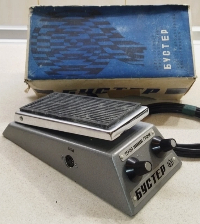 |
This is my example with the original box and the 5-pin DIN cable that was provided with the pedal. I am missing the original manual but that's kind of to be expected for something that has been sitting around since 1978. |
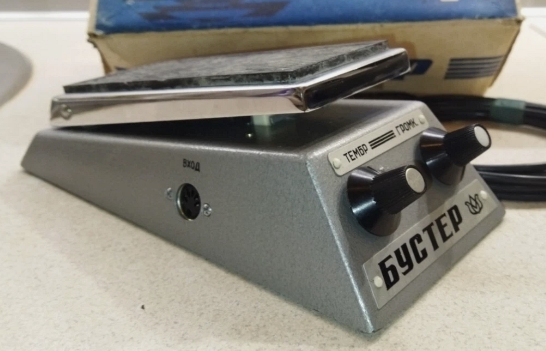 |
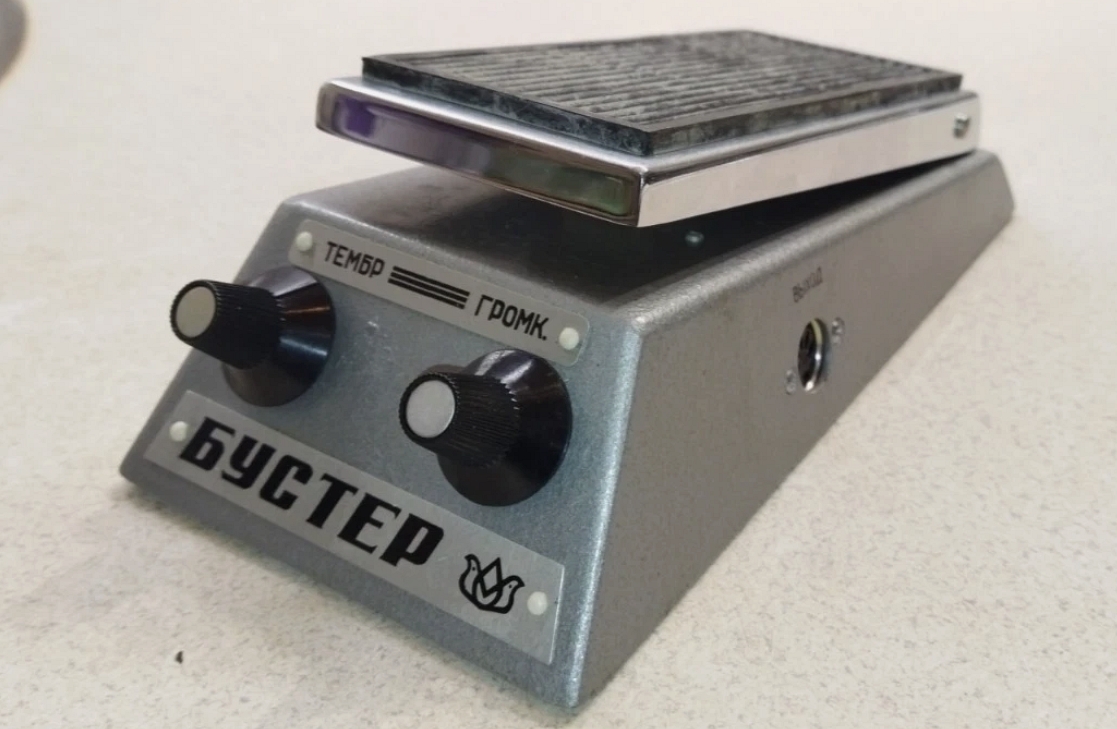
One interesting thing to note is the little plastic "rivets" that fasten the two nameplates to the enclosure are white. On the vast majority of Kazan pedals I have seen, these are black. |
 |
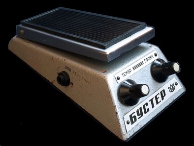
The Kazan Booster shares the same enclosure as the Kvaker and Vibrato pedals. The only difference is that the "treadle" is different. It is only used to switch the effect on/off, in a similar manner to the Riga "Voila" compressor-sustainer pedal. |
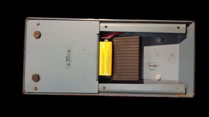 |
Here is the bottom with the battery cover removed. The 9V battery goes in between the foam and the vertical portion of the other half of the bottom cover. |
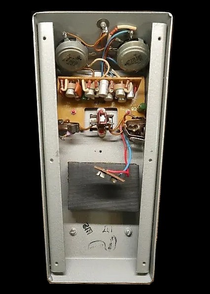 |
With the other half of the bottom cover removed we can see the PCB. It is a similar arrangement to the Kvaker wah pedal, with a vertically mounted daughter board attached to the larger PCB underneath. |
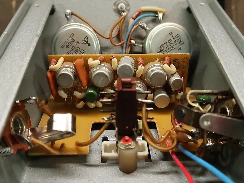 |
From this angle you can see that most of the components are on the vertically mounted daughter board. It uses the same sort of weird 12-pin DPDT push button switch as the Univox Uniwah (these are referred to as type "P2K"). It is NOT wired as true bypass but it could easily be converted. The way it was implemented, I would not at all be worried about the switch breaking in normal, reasonable use. |
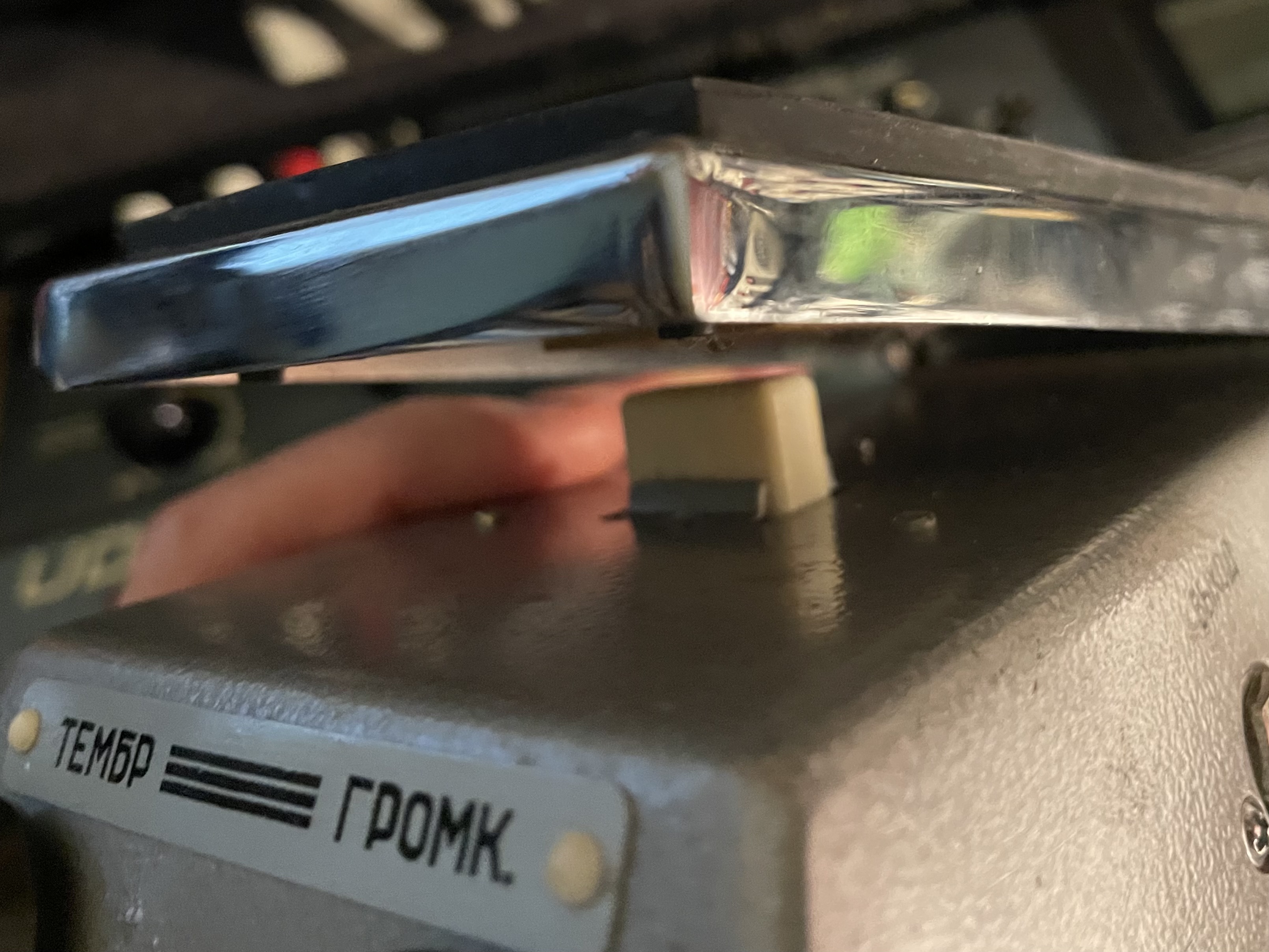 |
This white push button protudes thru the heavy duty steel enclosure and is what actuates the switch when you press down on the "treadle". There are supports on two sides which are an integral part of the stamping. These help support and guide it. The switch might not survive if you put your full weight on it, so be careful with it. It's not as delicate as it may appear but it's also not bulletproof. In hindsight, having some sort of over travel stop on the enclosure would have been a good idea. |
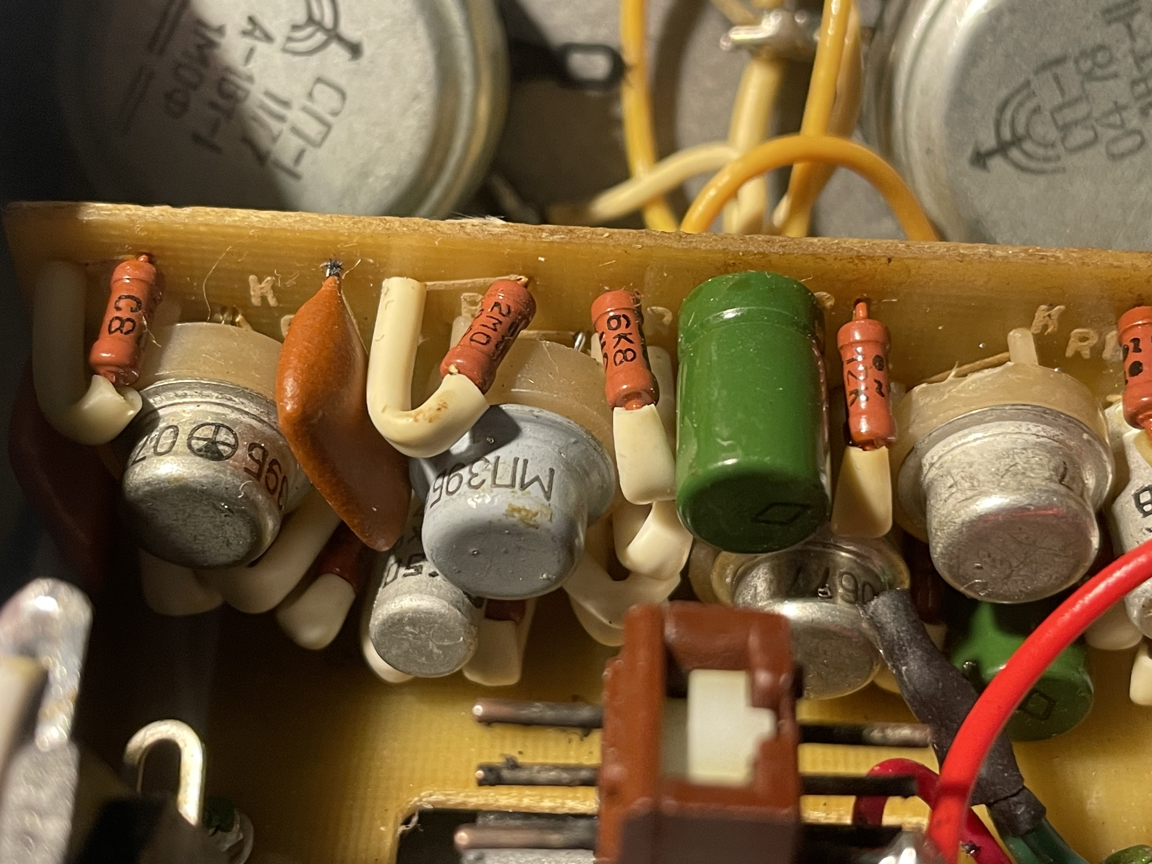 |
This is a closer view of the PCB in my own example. The date codes on the pots are 1977 & 1978 and the box it came in also has a date stamp of 1978. The distinctive logo on the pots indicate that they were manufactured by "Omega / Rezistor" in Unecha, Russia. This factory was in operation from 1958-2000. It now sits abandoned . |
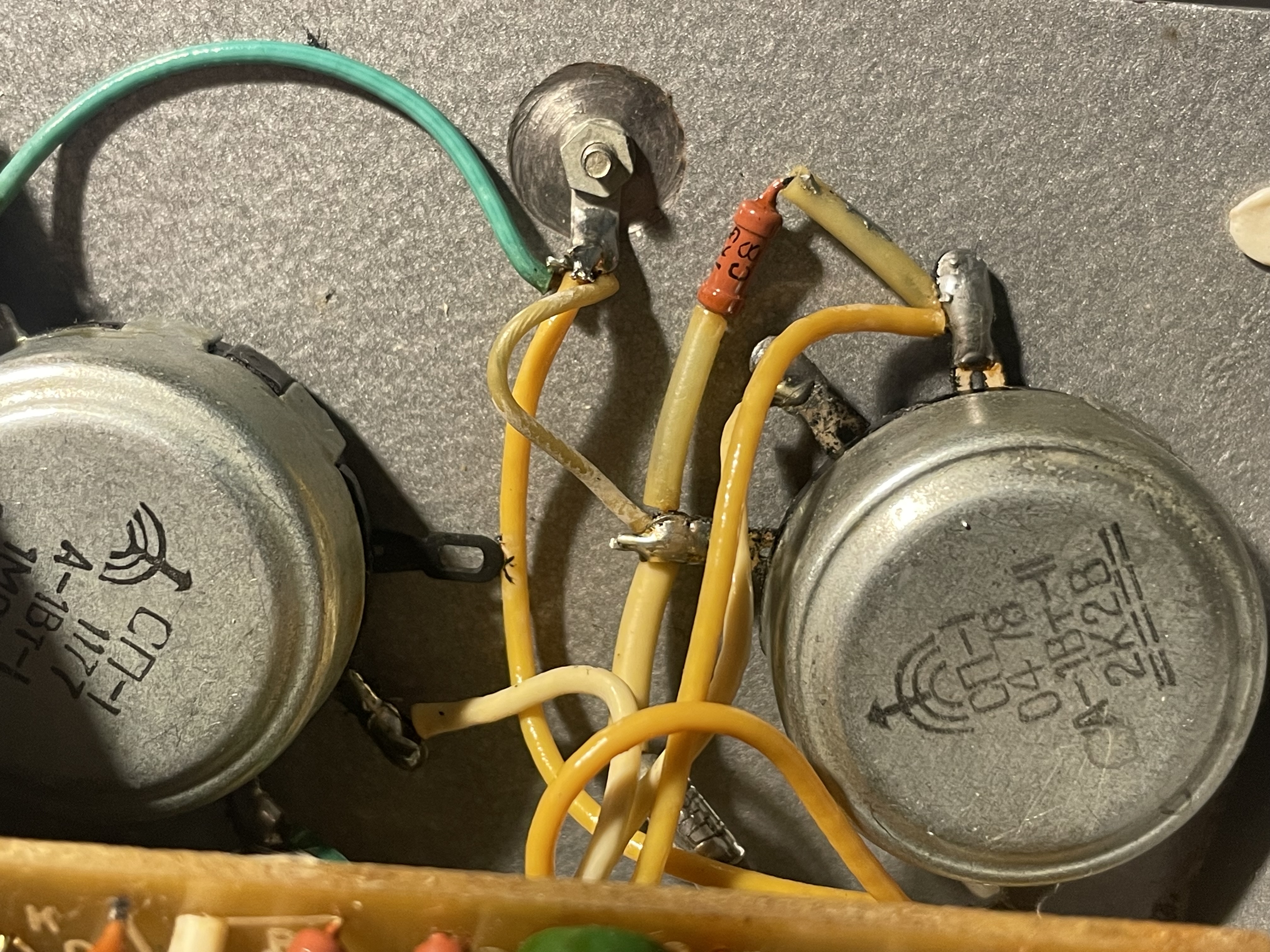 |
Close up of the pots in my own example. One interesting thing to note is the addition of a 1.5K resistor in parallel with the 2.2K Level pot, which effectively makes it approx. 1K. This is not shown on the factory schematic. Removing it will make the pedal louder, but it will also make it a lot noisier. I kept mine as it came from the factory. I suspect they added this due to variability of transistors, to keep the output at some specific maximum level. |
That's pretty much all I know about this particular "rare" Kazan pedal. I have hardly any info on the three transistor version, well really
nothing at all. If you have one and want to contribute to this webpage, please send me an email via the link on my home page.
Shown below is a diagram of the PCB and wiring. This image with inversed colors is linked below (graphics on white background).
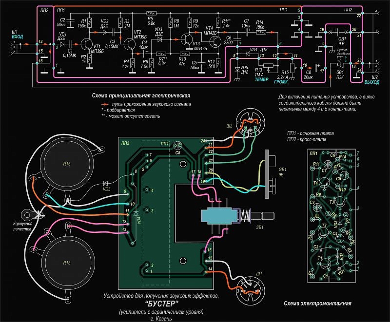
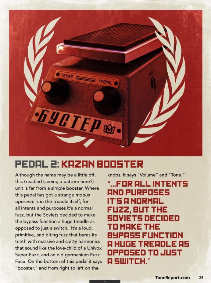
Knowing the intricacies of this circuit, I beg to differ that this is just a "normal fuzz" as noted in the article below!
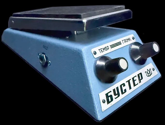
These were available in at least three colors. The vast majority I have seen are silver, but there is also a light / med blue version and a gold version as well. I have no idea if they correlate to a certain time period or not. Shown below are the gold and blue versions of the Kazan Booster. I can't tell if there was two blue versions or if the differences I see in various pictures are just due to lighting, etc. Some seem like a sky blue and some seem to be a slightly darker shade of blue. Of course, these color variants are deemed more rare, and hence the asking prices are higher.
 |
Kazan Booster 3-transistor Schematic Kazan Booster 4-Transistor Schematic |
 |